Key takeaways
- Start with the classification and required equipment protection level for the exact mounting point; gas and dust approval are separate checks.
- A higher EPL meets only the protection-level check. Group, temperature, ambient range, certificate conditions and local acceptance must also match.
- Intrinsic safety applies to the complete connected circuit, including the reader, associated apparatus and cables; the approved system determines the interface arrangement.
- ATEX documentation depends on the conformity-assessment route. An IECEx claim should be checked against the current online Certificate of Conformity.
- TP-110 has supplier-reported Ex markings but no verified ATEX or IECEx certificate in our current records; hazardous-area suitability remains unverified.
Specify a hazardous-area card reader from the classification of its mounting point and verified conformity documents for the exact equipment. An Ex marking describes claimed protection; it does not by itself prove certification or approve a connected installation. In particular, our current TP-110 records contain supplier-reported markings but no verified ATEX or IECEx certificate.
This guide helps purchasers prepare a specification and document review. The site’s competent hazardous-area designer determines the equipment, circuits and installation requirements under the applicable national rules and standards.
Start with the zone and substances
Obtain the classification drawing for the reader, lock, junction box and cable route. A facility name such as “refinery” does not classify every gate or room. Gas and dust zones describe different atmospheres, and approval for one does not establish approval for the other.
The usual zone-to-EPL relationship and EU category selection are summarized below. The EU workplace rules also require suitability for the atmosphere and the site’s explosion-protection assessment; the table is not an installation approval.
| Location | Atmosphere occurrence | Usual acceptable EPLs | EU equipment categories for that atmosphere |
|---|---|---|---|
| Gas Zone 0 | Continuous, frequent or prolonged | Ga | 1G |
| Gas Zone 1 | Occasional during normal operation | Ga or Gb | 1G or 2G |
| Gas Zone 2 | Unlikely during normal operation; brief if present | Ga, Gb or Gc | 1G, 2G or 3G |
| Dust Zone 20 | Continuous, frequent or prolonged dust cloud | Da | 1D |
| Dust Zone 21 | Occasional dust cloud during normal operation | Da or Db | 1D or 2D |
| Dust Zone 22 | Unlikely dust cloud during normal operation; brief if present | Da, Db or Dc | 1D, 2D or 3D |
A higher EPL can satisfy the level requirement in a less demanding zone, subject to the other selection conditions. It does not automatically satisfy gas or dust group, temperature, environment or local acceptance. Underground mining equipment is outside this guide’s scope.
For US installations, check the accepted Class/Division or Zone approval and installation requirements. An ATEX or IECEx document alone does not demonstrate compliance with OSHA’s hazardous-location requirements.
Read the complete marking
The following is an illustrative gas marking, not a statement that a catalog product has been certified: II 1G Ex ia IIC T4 Ga.
| Element | What to verify |
|---|---|
| II 1G | ATEX surface-industry equipment group, category and gas designation |
| Ex ia | Intrinsic-safety protection concept and level; confirm the cited standard and scope |
| IIC | Gas subgroup; match it to the actual substances and any certificate restrictions |
| T4 | Gas temperature class: maximum surface temperature 135 °C under specified conditions |
| Ga | Gas EPL; check it against the site’s requirement |
| Ta or Tamb | Approved ambient range, read with the certificate and instructions |
| Certificate X suffix | Specific Conditions of Use must be reviewed and implemented |
| Certificate U suffix | Component certification with limitations; not a complete equipment approval |
Gas subgroups IIA, IIB and IIC are separate from dust subgroups IIIA, IIIB and IIIC. Group selection follows the relevant hierarchy, but a gas-group marking does not supply dust approval. For a combined gas-and-dust installation, review both markings and the respective conditions.
Gas temperature classes describe surface-temperature limits, not the outdoor temperature at which the reader will work:
| Gas class | Maximum surface temperature |
|---|---|
| T1 | 450 °C |
| T2 | 300 °C |
| T3 | 200 °C |
| T4 | 135 °C |
| T5 | 100 °C |
| T6 | 85 °C |
Dust selection needs the tested dust-cloud and dust-layer ignition properties, anticipated accumulation and the equipment’s documented temperature conditions. Do not substitute a gas T-class or interpret a layer-qualified dust marking from plain text alone. The required margins and any thicker-layer assessment belong in the site’s design review.
Obtain the approved ambient range explicitly. A general operating-temperature specification is not a certified Ex range, and missing marking information should not be filled with an assumed default. Cleaning, electrostatic charging, impact, corrosion and accessory conditions can also limit use.
Compare Ex i, Ex d and Ex e
Intrinsic safety, Ex i, controls electrical and thermal ignition energy in the assessed circuit. Levels ia, ib and ic use different fault-assessment requirements and generally correspond to Ga/Da, Gb/Db and Gc/Dc respectively. The overall equipment and system marking governs; an intrinsically safe subcircuit does not raise the protection level of an entire assembly.
Flameproof protection, Ex d, contains an internal explosion and prevents transmission through its designed enclosure and flame paths. The familiar db level corresponds to Gb. The d family also has other levels, so avoid treating the broad term “Ex d” as a universal zone rating. Entries, windows and enclosure construction must remain within the approved design.
Increased safety, Ex e, addresses equipment without unprotected ignition-producing arcs or sparks under the assessed conditions. The eb and ec levels differ. It often appears with another protection concept in an assembly; an Ex terminal compartment does not alone approve the reader electronics connected to it.
| Protection family | Procurement focus | Connection review |
|---|---|---|
| Ex i, IEC 60079-11 | Complete marking, protected circuits and required system assessment | Associated apparatus, circuit parameters, cables and any permitted system configuration |
| Ex d, IEC 60079-1 | Actual protection level, enclosure and permitted entries | Approved entry arrangement, cables, plugs and manufacturer instructions |
| Ex e, IEC 60079-7 | Actual protection level and scope of protected equipment | Termination, entry and assembly requirements in the approved design |
Encapsulation Ex m and dust enclosure protection Ex t are additional concepts. Potting or an IP label alone does not establish either. These distinctions follow the IECEx protection-technique overview; check the current standards and the equipment’s own documents for the project.
Request the right conformity documents
For an ATEX electrical reader, request the EU Declaration of Conformity, instructions and evidence of the applicable conformity-assessment route. Category 1 and category 2 electrical equipment normally use EU-type examination with the applicable production procedure; unit verification is an alternative route. Category 3 can use internal production control. Category 2 non-electrical equipment follows a different route, so “every category 1 or 2 item needs the same certificate” is inaccurate.
The notified-body number follows the CE mark when that body participates in production control. A type-examination body’s involvement alone does not establish which number belongs there. Check the route and issuing body instead of applying a blanket rule to all categories. The ATEX Directive and European Commission guidance explain these distinctions.
For IECEx, check the current online Certificate of Conformity, its exact equipment description, issue, status, annexes and linked report references. A downloaded copy may have been superseded. A U component certificate is not a stand-alone approval for a finished reader; X identifies conditions requiring attention. See the IECEx certificate guidance.
Document review should answer:
- Does the approval cover the exact model, keypad option and hardware configuration?
- Do gas/dust scope, EPL, temperatures and ambient limits match the site?
- Are the instructions, schedules and Specific Conditions of Use available?
- Is the claimed IECEx certificate current in the online system?
- Are the circuit parameters and installation documentation sufficient for the proposed connections?
Review the connected circuit and installation
A common arrangement places ordinary controllers and supplies in an unclassified area, reducing equipment inside the zone. This is a design choice, not a universal requirement that every controller or barrier be outside. Equipment installed inside needs suitable protection and approval for that location. Square-bracket associated-apparatus markings describe protected connected circuits; review the apparatus’s own location suitability separately.
For an entity-based IS loop, obtain reader input parameters such as Ui, Ii, Pi, Ci and Li and the associated apparatus’s output and permitted external-circuit values. The designer checks them with cable capacitance and inductance and any permitted combined L/C pairs. Multiple sources or a different system concept require the relevant assessment rather than a generic calculator. IEC 60079-25 covers intrinsically safe systems; installation requirements are addressed in IEC 60079-14.
Account for power, data, control lines and accessories in the approved circuit arrangement. A product statement that no external barrier is needed is insufficient without the supporting design documents. Functional Wiegand or RS485 communication through an interface must also be checked; a successful bench test does not prove explosion protection. Our reader-interface guide covers the functional interface differences.
Zener barriers commonly depend on a high-integrity IS earth. Galvanic isolation can avoid that particular dependence, but does not remove every protective bonding, shielding or functional-earthing requirement. Follow the selected apparatus instructions and site design. Do not turn a general earth-resistance figure or terminal-separation distance into a universal installation rule.
The same discipline applies to cable entries, unused openings, segregation and bonding: use the selected protection concept, applicable installation standard and manufacturer instructions. Live work is not authorized merely because a circuit is intrinsically safe. Maintenance and isolation procedures require their own competent assessment.
Locks, exit devices and door contacts need evaluation too. Some simple passive devices may be accepted as simple apparatus in an assessed IS system; powered or illuminated assemblies must not be assumed to qualify. Confirm release behavior and emergency egress independently of credential-reading success.
TP-110: current evidence and ordering status
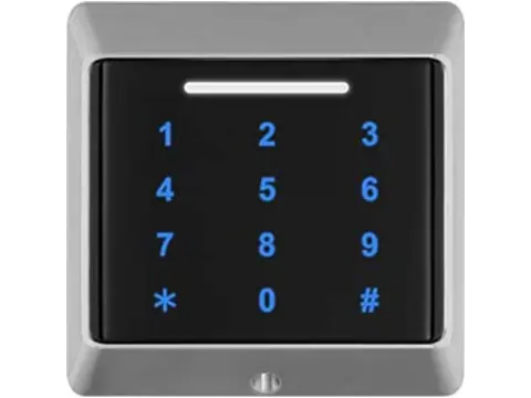
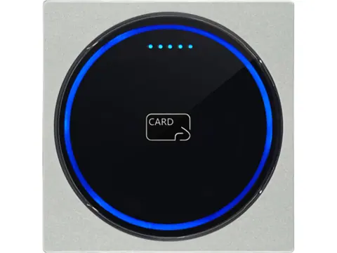
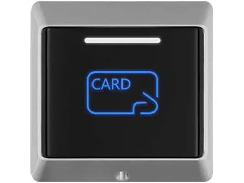
TP-110’s supplier documentation reports gas marking Ex ia IIC T6 Ga and a dust marking, along with LF/HF reading and Wiegand 34/66 or RS485 output. We have no verified ATEX or IECEx certificate, certified system drawing or entity-parameter set in the current project records. We therefore cannot substantiate a specific zone installation or the supplier’s barrier-free claim.
Treat TP-110 as a document-review candidate, not a verified hazardous-area recommendation. If procurement requires certified Ex equipment, leave the selection open until acceptable evidence is received and reviewed. The tamper-proof reader category also includes ordinary security readers, which must not inherit Ex suitability from their category placement.
RFQ checklist and next steps
- Classification for each mounting point and the required approval scheme
- Actual gas/dust groups, ignition data and required EPL/category
- Ambient and environmental conditions, including cleaning and dust accumulation
- Exact equipment configuration and complete conformity documents
- Approved circuit/interface arrangement and cable requirements
- Credential sample, required data and controller input format
- Evaluation of locks, exit devices, contacts and accessories
- Competent design, installation and initial-inspection responsibilities
Send these requirements through the RFQ form. We can review catalog interfaces and the documents available for a candidate, identify missing evidence and arrange safe-area bench samples. Classified-area approval and final circuit selection remain with the project’s qualified review.
Sources
Technical and regulatory review date: October 1, 2026. This page summarizes procurement checks; it is not a substitute for the applicable standards or an equipment certificate.
Frequently asked questions
What is the difference between flameproof and intrinsically safe?
Flameproof protection, Ex d, uses an enclosure and flame paths to prevent an internal explosion from igniting the surrounding atmosphere. Intrinsic safety, Ex i, limits ignition-capable energy in the circuit under its specified assessment conditions. Neither term alone establishes installation suitability.
Can I use a Zone 1 reader in Zone 0?
A reader approved only at EPL Gb does not meet the usual Zone 0 requirement for Ga. Check the complete marking and accepted conformity documents; a protection code or a catalog zone claim alone is insufficient.
Does every intrinsically safe reader need an external barrier?
The approved circuit design determines that. A conventional entity-based loop often uses associated apparatus, but a separate barrier must not be added or omitted by assumption. Obtain the certificate, instructions and system documentation for every connected circuit.
What do T4 and T6 mean?
For gas equipment, T4 corresponds to a maximum surface temperature of 135 °C and T6 to 85 °C under the certified conditions. These are not ambient operating limits and do not replace a dust-temperature assessment.
Is an IP66 or IP67 reader suitable for a hazardous area?
An ingress rating does not establish explosion protection. The equipment and installation need evidence appropriate to the classified location, substances, temperatures and applicable approval scheme.
Is TP-110 verified as ATEX or IECEx certified?
No verified ATEX or IECEx certificate is available in our current records. The supplier reports Ex ia markings, but we cannot substantiate a specific zone approval, certified ambient range or barrier-free installation from that marking alone.
Want a second opinion on your spec?
Send us your controller, credential type and environment — we'll recommend compatible hardware and quote within 24 hours.