Key takeaways
- IH-120, IH-130 and IH-140 have published reading ratings only; writing support and distance need separate confirmation.
- IH-110 lists Ethernet Modbus TCP and serial Modbus RTU, with recorded read/write distances for specified reference tags.
- A Modbus interface does not establish the RFID data map, tag operations or compatibility with your PLC and program.
- Qualify the actual tag, installed gap, surrounding metal, host timing and failure behavior before approving production hardware.
- Request the ordered firmware, communication map, cable pinout, configuration instructions and sample acceptance criteria together.
Choose an industrial HF RFID reader by the tag operation, the PLC communication path and the installed reading gap. IH-120, IH-130 and IH-140 are RS485 Modbus RTU heads with published reading ratings; IH-110 adds Ethernet Modbus TCP and documented read/write references. Use them as sample candidates until the exact tag, firmware, data map and host behavior meet the production task.
Shortlist the four industrial HF options
All four operate at 13.56 MHz, list ISO/IEC 15693 and ISO/IEC 14443A, and have integrated PCB antennas. They serve identification points on carriers, tooling or fixtures; sharing a frequency does not establish the memory operations required by your process.
On small screens, scroll the comparison tables sideways to read all columns.
| Candidate | Listed host interface and power | Mechanical fit | Reading reference |
|---|---|---|---|
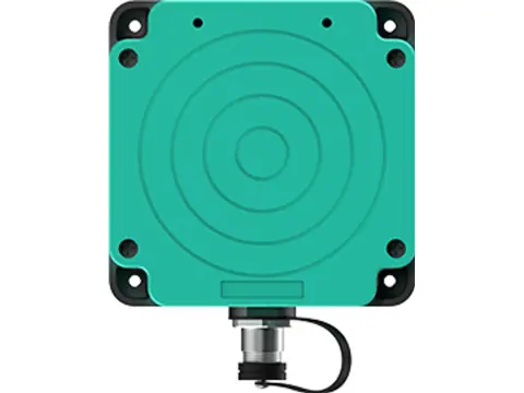
| IH-110 reader/writer | Ethernet Modbus TCP; serial Modbus RTU; 9–24 V DC, 3 W max | 95 × 95 × 40 mm; industrial breakout cable | Up to 110 mm with a Ø30 mm ISO/IEC 15693 industrial tag; separate card figures below |
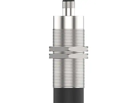
| IH-120 M30 head | RS485 Modbus RTU; 24 V DC, 2 W max | Threaded M30 barrel, Ø30 × 65 mm; M12 connection | 0–80 mm, tag-dependent; approximately 45–60 mm with a Ø30 mm industrial tag, depending on build |
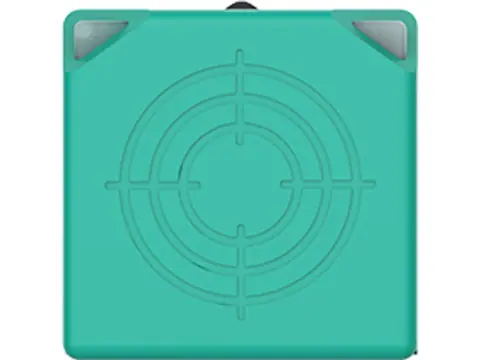
| IH-130 square head | RS485 Modbus RTU; 24 V DC, 2 W max | 40 × 40 × 45 mm; M12 connection | 0–80 mm, tag-dependent; approximately 60 mm with a Ø30 mm industrial tag |
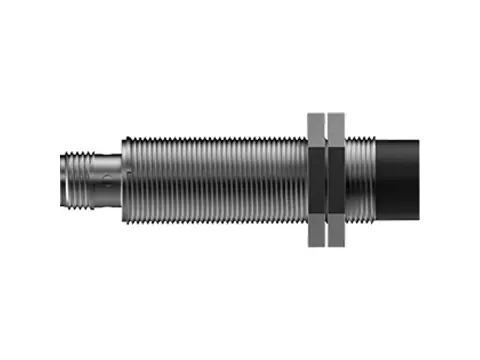
| IH-140 compact head | RS485 Modbus RTU; 24 V DC, 2 W max | Threaded barrel, Ø30 × 60 mm; M12 connection | 0–50 mm, tag-dependent; approximately 35 mm with a Ø30 mm industrial tag |
Choose the mounting format before fixing bracket positions. A square face, M30 barrel and larger networked enclosure require different space and cable routing. The records list IP67 for all four, with operating temperatures of –40 to +70 °C for the three heads and –40 to +85 °C for IH-110; confirm the actual exposure and mounting requirements.
Specify the full build in the quote: IH-120-RS, IH-130-RS or IH-140-RS; IH-110-NET for the wired reader, or IH-110-NET-WF if the optional Wi-Fi build is required. Wi-Fi is not standard, and a network option does not replace host integration testing.
Separate identification from writing process data
Define whether the station reads a tag identifier, reads application memory or writes a lot number or process result. Provide the exact tag chip and required data fields, including any access conditions. Protocol support alone does not prove that the required memory commands are implemented.
IH-120, IH-130 and IH-140 have published reading ratings only. Do not use their reading distance as a write specification. Request confirmation of write capability and a tested write distance for the exact tag if writing is required.
IH-110 has the following recorded references:
| Reference tag | Maximum listed read distance | Maximum listed write distance |
|---|---|---|
| Ø30 mm ISO/IEC 15693 industrial tag | 110 mm | 100 mm |
| Blank ISO/IEC 14443A card | 60 mm | 50 mm |
These are conditional product figures, not guaranteed distances with another tag, mounting surface or moving carrier. Confirm supported memory operations and verify written data on samples. Keep a read-only identification task distinct from a task that requires successful memory writes before the machine proceeds.
Match Modbus RTU or TCP to the actual host
The three heads list RS485 Modbus RTU. Check the PLC’s installed serial hardware and RTU support; request the reader’s supported baud rate, parity, stop bits, addressing and wiring instructions. The records list 9600–115200 bit/s, but do not establish a default configuration or the capacity of a complete bus.
The official Modbus serial-line guide requires compatible transmission mode and serial settings on a bus. It does not provide the product’s settings. Confirm termination, cable routing and the planned devices against the actual hardware documentation.
IH-110 lists Modbus TCP over Ethernet and Modbus RTU over serial interfaces, as well as TCP/UDP. The Modbus TCP implementation guide describes TCP framing with an MBAP header, which differs from serial RTU framing. A generic TCP/UDP connection is not automatically a Modbus TCP service. If a gateway connects an RTU head to Ethernet, confirm its address mapping, Unit Identifier handling and timing with the reader and PLC; do not assume a transparent, tested combination.
Obtain the RFID data map before programming the PLC
Request documentation for the ordered model and firmware. It should define supported function codes, register addresses, tag data length and representation, operation requests, completion status and failure results. Ask for request/response examples using the intended tag operation.
The Modbus application specification defines coils/registers and zero-based PDU addresses, while their binding to a device application depends on the implementation. Check how the reader’s documented addresses correspond to the PLC library’s numbering. Writing a Modbus register does not by itself prove that the device writes RFID tag memory.
Agree on UID byte order and any memory-data packing, result validity, timeout handling and what happens after a tag leaves. Ask how the host distinguishes fresh data, no tag and a failed operation. No reader-specific register map, endpoint defaults or certified PLC combination is established by the current public product records.
All four list API kits with C, C# and Java examples. Request the available version, instructions and applicable software requirements with the sample; those examples do not establish a PLC function block or a ready-to-use production program.
Qualify the installed gap, metal and cable arrangement
Test the actual tag on its carrier with the reader in the proposed bracket. Include minimum and maximum gaps, orientation changes, nearby metal and the real movement or stopping position. A larger reference tag’s distance does not apply automatically to a smaller or embedded tag.
Record the time available for identification and, where required, writing and verification. No line speed, read-cycle guarantee or tag throughput is provided for these four products. For wider installation context, see RFID asset and tool tracking; a bare-board design has different requirements covered by the reader-module buying guide.
Confirm cable pin assignments and mating parts before wiring. The three heads specify M12 female-connector harnesses; IH-110 uses its documented breakout cable. Its two inputs and two outputs need electrical-rating confirmation before connecting sensors or signals.
Plan power at the device, including cable losses and startup. IH-110 lists up to 1 A startup current in addition to its 3 W consumption figure; request startup conditions and any optional-load requirements. Confirm the supplied accessories separately rather than assuming that a power supply, gateway or complete harness is included.
Use a bench and installed-sample acceptance checklist
Agree on pass/fail criteria before testing, then record the reader build, firmware, tag, host and configuration alongside the results.
- Verify the connection. Check power and cable assignments, establish the chosen RTU/TCP path and confirm the documented addressing and data representation.
- Verify the intended data. Compare the returned identifier or memory fields with a known sample. Confirm byte order, length, leading zeros and the host’s interpretation.
- Check physical variation. Repeat on the real carrier and bracket at the required gaps and orientations, with relevant metal nearby. Check unintended neighboring tags.
- Check operation timing and failures. Evaluate the actual dwell time, no-tag result, communication loss, reader/host restart and removal of a tag. Confirm that old data is not accepted as a new read.
- Verify writing if required and supported. Write the agreed fields, read them back and test interrupted or unsuccessful operations. Separate transport success from completion of the RFID write.
- Approve the recorded combination. Identify unresolved cases and repeat affected checks after changes to firmware, tags, mounting, cables or host settings. Keep the accepted configuration with the order.
Copy this information into the RFQ
Use the following fields for a sample request and production quote:
- Candidate/build: IH-110/120/130/140, full variant, sample quantity and project quantity.
- Host: PLC or other host model, communication module, software/library version and RTU or TCP requirement.
- Tags and operation: chip, protocol, sample tags, identifier or memory fields, reading/writing and access requirements.
- Installation: drawing, carrier material, bracket, orientation, working-gap variation and nearby metal.
- Timing: stopped or moving tag, available dwell time, intended polling and required failure handling.
- Electrical: power arrangement, cable length, connector/harness needs and any requested I/O.
- Documents: firmware-specific communication map, command examples, pinout, configuration instructions and available software kit.
- Acceptance and supply: sample tests, environmental requirements, packing/accessories, production quantity and requested delivery date.
Request samples and a quote with this brief. Confirm missing parameters and the accepted configuration in the order specification before approving production hardware.
Sources
Checked 2026-10-03. These standards explain communication boundaries; they do not establish product certification, RFID commands or a validated PLC combination.
- Modbus Application Protocol Specification V1.1b3, sections 4.3–4.4: data model, addressing and device-application mapping.
- Modbus Serial Line Protocol and Implementation Guide V1.02, section 2.5: transmission modes and serial configuration.
- Modbus Messaging on TCP/IP Implementation Guide V1.0b, section 3.1: TCP framing and gateway identification.
Frequently asked questions
Will a Modbus RFID reader work with any PLC?
Compatibility needs evaluation with the actual PLC, communication module and program. Confirm RTU or TCP support, the reader's firmware-specific data map, supported operations and result handling. A matching protocol name does not establish a tested combination.
Can IH-120, IH-130 and IH-140 write process data?
Their published ratings cover reading only. Write support, supported tag-memory operations and write distance need confirmation. IH-110 has recorded read/write references, but its required operations must also be verified with your exact tag and host.
Can these industrial HF heads read UHF asset tags?
No. These four products operate at 13.56 MHz and list ISO/IEC 15693 and ISO/IEC 14443A. They are not EPC Gen2 UHF readers; select a tag with a supported HF protocol and confirm the data operation required.
Can I install the head at its maximum listed distance?
Treat the figures as tag-dependent references, not an installation guarantee. Test the actual tag, bracket, orientation, metal surroundings and motion. For writing, confirm a separate working distance rather than using a reading rating.
Do all four products use the same M12 cable?
No. IH-120, IH-130 and IH-140 list M12 connections with female-connector harnesses, while IH-110 lists an industrial breakout cable. Request the exact pinout, mating cable and packing list; power supplies, gateways and other accessories must be confirmed in the quote.
What should a PLC integration sample request contain?
Include the reader SKU and build, PLC and interface module, tag samples, required UID or memory operation, installation drawing, working gap and timing requirement. Ask for firmware-specific communication documentation and agree on correct data, no-tag, fault, restart and any write/read-back tests.
Want a second opinion on your spec?
Send your application, existing hardware, interfaces and quantities — we'll review the requirements and quote within 24 hours.