Key takeaways
- A 280 kg (600 lb) maglock suits most interior single doors; choose a 500 kg (1200 lb) class lock for exterior, perimeter, heavy or high-traffic doors.
- Rated holding force is a straight-pull figure with a fully seated armature at rated voltage; misalignment, dirt and voltage drop reduce it on site.
- Door swing relative to the lock side decides the bracket: none for pull-side mounting, ZL for push-side, L for narrow frames, U clamps for frameless glass.
- A 280 kg lock draws about 0.5 A at 12 V DC or 0.25 A at 24 V DC for as long as the door is locked; size the supply at total load plus 25–50% headroom.
- Maglocks are always fail-safe, so an egress release, a fire-alarm interface and a door closer belong in every installation.
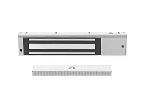
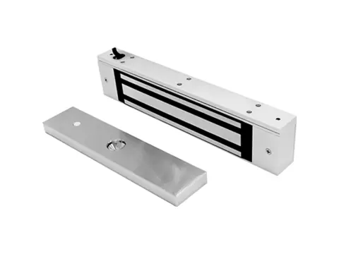
For most interior single doors, the best magnetic lock is a 280 kg (600 lb) surface-mount unit on the right bracket; step up to a 500 kg (1200 lb) class lock for exterior, perimeter, heavy or high-traffic doors. After holding force, the choice comes down to fit — door swing, frame depth and door material decide the bracket — and to features such as a lock-status output that lets your controller confirm the door is actually secure. This guide walks through each decision and ends with a spec comparison table and a bulk-buying QC checklist.
Holding force: 280 kg (600 lb) vs 500 kg (1200 lb)
Holding force is the static pull a maglock resists before the armature separates from the lock face. Strictly it is a force (kgf or lbf), measured as a straight pull, perpendicular to the lock face, with the armature flat and fully seated at rated voltage. That is a laboratory best case, and the number on the box is also a class label rather than an exact conversion.
| Nominal class (as labeled) | Exact conversion | Typical doors | Buying note |
|---|---|---|---|
| 180 kg / 350 lb | 180 kgf ≈ 397 lbf | Cabinets, light interior doors | Labels vary; compare kg figures |
| 280 kg / 600 lb | 280 kgf ≈ 617 lbf | Offices, corridors, standard interior single doors | The usual default for interior access control |
| 500 kg / 1200 lb | 500 kgf ≈ 1,102 lbf | Main entrances, perimeter and exterior doors, heavy or tall doors | The lb label sits about 9% above the kg conversion |
When you compare quotes from different sources, compare in one unit. If a specification states a minimum force in lbf, convert the tested kg value (1 kgf ≈ 2.2 lbf) rather than trusting the label. In North America, ANSI/BHMA A156.23 grades electromagnetic locks on tested holding force and other criteria; if a specification calls for a BHMA grade, ask for the test documentation.
On site, a lock holds less than its rating when:
- the armature is misaligned or does not sit flat on the lock face;
- paint, dirt or rust sits between the mating faces;
- cable voltage drop leaves the coil below its rated voltage;
- the door flexes, so force applied low on a tall door peels the armature away from its corner.
That last point is why exterior and heavy doors justify the 500 kg class even when the 280 kg figure looks ample on paper. You can browse the current range on our magnetic locks and brackets page.
Single vs double doors, surface vs mortise mounting
A single door takes one lock at the top corner of the frame on the side opposite the hinges, where the lock sits farthest from the hinge line and resists the door’s swing with the most leverage.
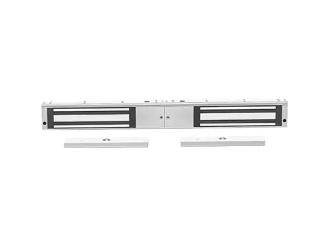
Double doors (pairs) normally use a double maglock: one long housing with two independent coils and two armatures, one per leaf. Each coil carries the full class rating — for example 2 × 280 kg — and the two coils usually run in parallel from the same controller output, which doubles the current. If the pair has an overlapping astragal, the leaves must close in the right order (a door coordinator does this) or one armature will not seat.
Surface mounting is the default: the lock body screws under the frame header and the armature bolts to the door. It suits retrofits and is the easiest to service. Mortise (concealed) maglocks recess the lock body into the frame header so little or nothing projects below it. They look cleaner and expose less to tampering, but they need enough header depth, more installation labor and a model that fits the frame profile. Confirm frame dimensions before specifying one.
Glass, wood, metal and gate doors
Framed glass doors (aluminum stiles and top rail) take a lock on the header and the armature on the top rail. Narrow top rails or shallow headers often need an L bracket.
Frameless glass doors cannot be drilled on site because tempered glass cannot be drilled after tempering. U-shaped clamp brackets grip the glass edge and carry the armature. A double-acting door that swings both ways is a poor fit for a maglock, which bonds on one face only; an electric drop bolt into the header or floor is the usual answer. See our electric bolt locks for that case.
Wood doors should be solid-core. The armature fixes with a through-bolt and sleeve nut, which is much harder to remove from the non-secure side than a wood screw. Hollow-core doors need a reinforcing block where the bolt passes through.
Metal doors use the same through-bolt fixing. Mount the armature on its rubber washer so it can rock slightly and sit flat against the lock face; do not clamp it rigid.
Gates need an outdoor-rated lock: a stated IP rating such as IP65 or IP67, sealed or potted electronics, and a housing that resists corrosion. Gates sag and move in the wind, so plan a rigid post bracket and check alignment after installation.
Whatever the door, a maglock only locks when the door is fully closed. Every maglocked door needs a correctly sized door closer.
Bracket selection summary
The bracket depends on which way the door swings relative to the side where you mount the lock — normally the secure side. Supplier listings often describe the ZL bracket as “for inward-opening doors,” which is ambiguous, so define swing relative to the lock before ordering.
| Door situation | Bracket | What it does |
|---|---|---|
| Door swings toward the lock side (pull side), header soffit deep enough | None (standard mount) | Lock body under the header, armature on the door face |
| Door swings away from the lock side (push side) | ZL (Z plate + L bracket) | L bracket drops the lock below the stop; Z plate brings the armature out to meet it |
| Header or top rail too narrow for the lock body | L bracket | Extends the mounting surface for the lock body |
| Frameless glass door | U bracket (glass clamp) | Holds the armature on the glass without drilling |
Brackets are sized to a lock body, so a bracket made for one holding-force class may not fit another. Order locks and brackets together. The maglock bracket guide covers each type in detail.
Features: door status signal, LED and time delay
- Lock-status (bond) output. A sensor confirms the armature is fully bonded to the lock face. This distinguishes “door closed” from “door locked,” catching an obstruction or a low supply voltage. It is usually a dry contact (NO/NC/COM).
- Door-status output. Reports only whether the door is closed. Listings use “door status” and “lock status” loosely, so check which one the datasheet describes before you map it to a controller input.
- LED indicator. Shows locked or unlocked at a glance, which speeds commissioning and troubleshooting.
- Time delay. Some locks add a relock or unlock delay; many do not, and the controller or power supply handles timing. Delayed-egress locking is a separately regulated function — use only products listed for it, where the code allows.
- 12/24 V DC operation. Dual-voltage locks select 12 V or 24 V with a jumper or by wiring, or detect it automatically. Power is the same either way; current halves at 24 V.
- Surge suppression. Follow the exact lock / output manufacturer’s suppression instructions. Do not automatically add a diode or MOV; a parallel diode can interfere with quick release on some maglocks. The magnetic lock wiring diagram guide explains the model-specific check.
Egress, fire-alarm and code checks
Maglocks are fail-safe by design: remove power and the door releases. That is why codes accept them on exit routes — but only with defined release arrangements. See fail-safe vs fail-secure locks for the door-by-door decision.
In the US, NFPA 101 and the International Building Code allow electromagnetic locks on egress doors under specific arrangements. The common one is sensor release: a sensor on the egress side unlocks the door as someone approaches, loss of power unlocks it, and fire-alarm or sprinkler activation releases it. A manual button marked PUSH TO EXIT also cuts lock power directly, independent of the access control electronics, for at least 30 seconds. Another route is door-hardware release, where a switch in the lever or panic bar cuts lock power. Requirements vary by code edition and occupancy, and the authority having jurisdiction has the final say.
Specifications in North America often call for UL 294 listing (access control system units); ask for the listing evidence rather than assuming it. In Europe, hardware added to a fire-rated door set must stay within the door’s fire test evidence (for example EN 1634-1), so check with the door supplier before drilling. Electrically controlled exit systems on escape routes fall under EN 13637.
Current draw and power-supply pairing
A maglock draws current continuously for as long as the door is locked. The 280 kg locks we supply draw about 0.46–0.50 A at 12 V DC and 0.23–0.25 A at 24 V DC, roughly 5.5–6 W. Larger locks do not always draw more, so read the datasheet for each model rather than scaling by holding force.
Size the supply at the total continuous load plus 25–50% headroom. For example, a double door with a 2 × 280 kg lock (about 1.0 A at 12 V), a reader (assume 0.1 A) and a standalone controller (assume 0.15 A) totals 1.25 A. With 50% headroom that is about 1.9 A, so a 3 A, 12 V DC unit from our access control power supplies covers it with margin.
Check voltage drop on long runs. Copper at 18 AWG (about 0.82 mm²) measures roughly 21 Ω per kilometer per conductor. A 30 m cable run has a 60 m loop, about 1.26 Ω, so a single 0.5 A lock loses about 0.6 V. A double lock at 1.0 A on the same cable loses about 1.3 V, which pushes a 12 V supply below the ±10% tolerance our locks specify. Use heavier cable or run the lock at 24 V: current halves, so the same run drops half the voltage, about a quarter as much in percentage terms.
A battery-backed supply keeps a fail-safe lock locked during a power cut. Confirm that behavior matches the site’s egress design, and make sure the fire-alarm input still removes lock power.
Buying in bulk: samples, QC checks and packaging
Order samples of each variant and bracket first, and install them on a real door before committing to volume. Agree your acceptance checks in writing so incoming inspection and our pre-dispatch testing measure the same things.
Incoming QC checklist
- Holding force verified by a straight-pull test with a calibrated gauge, armature flat, at rated voltage
- Coil current at 12 V and 24 V DC within the datasheet tolerance
- Coil temperature stabilizes after several hours energized (warm is normal)
- Door releases immediately at power-off, with no residual hold
- Status output switches correctly on NO and NC, and LED states match
- Voltage jumper or auto-select behaves as labeled
- Armature face flat, plated and free of rust, with a protective film in transit
- Fixing kit complete: through-bolt and sleeve nut, rubber washer, alignment pins, screws, drilling template, instructions
- Label shows holding force in kg and lb, voltage, current and SKU
- Individual boxes with foam protection; cartons marked with SKU and quantity
Private-label packaging, printed manuals and carton marking are available on request. Lead time depends on variant and quantity, and we confirm it on each quote.
Spec comparison table
Values for 280 kg locks reflect the models we supply. The 500 kg class varies more between models, so confirm those figures on the datasheet before sizing power or brackets.
| Spec | 280 kg single | 2 × 280 kg double | 500 kg single |
|---|---|---|---|
| Holding force (straight pull) | 280 kgf (≈ 617 lbf) | 280 kgf per leaf | 500 kgf (≈ 1,102 lbf) |
| Leaves held | 1 | 2 (independent coils) | 1 |
| Supply voltage | 12 or 24 V DC | 12 or 24 V DC | Usually 12 or 24 V DC; check model |
| Coil current at 12 V DC | About 0.46–0.50 A | About 0.92–1.0 A | Per datasheet |
| Coil current at 24 V DC | About 0.23–0.25 A | About 0.46–0.50 A | Per datasheet |
| Body size (typical) | About 210–250 × 42–48 × 26–29 mm | About 500 × 47 × 26 mm | Larger body; check header clearance |
| Typical doors | Interior single doors | Interior pairs, lobby doors | Exterior, perimeter, heavy doors |
| Common options | Door- or lock-status output, waterproof housing | Status output | Varies by model |
Next steps
Send us the door count, door type and swing, frame depth, required holding force, supply voltage and any status-output or bracket needs. We will confirm fit, match locks with brackets and a power supply, and ship samples for on-door testing before your volume order. Request a quote or samples and we will reply within 24 hours.
Suppression source
Only the suppression guidance was reviewed for this update. Securitron SAM installation manual, section 6.3 illustrates manufacturer-specific requirements; use the exact equipment manuals.
Frequently asked questions
How strong are magnetic locks?
Common classes are 280 kg (600 lb) and 500 kg (1200 lb) of straight-pull holding force, with lighter 180 kg locks for cabinets and light doors. The rating assumes a flat, fully seated armature at rated voltage; real resistance also depends on the door, frame and fixings.
Should I buy a 600 lb or a 1200 lb magnetic lock?
Use 600 lb (280 kg) for most interior doors and 1200 lb (500 kg) for exterior entrances, perimeter doors, and heavy or tall doors. Check header clearance first, because 1200 lb lock bodies are usually larger.
How many amps does a mag lock draw?
The 280 kg (600 lb) locks we supply draw about 0.46–0.50 A at 12 V DC and 0.23–0.25 A at 24 V DC, and a double-door lock draws twice that. Current flows continuously while the door is locked, so rate the power supply for continuous duty.
Can I put a magnetic lock on a glass door?
Yes. Framed glass doors mount the armature on the top rail, and frameless tempered glass uses U-shaped clamp brackets so nothing has to be drilled on site. Double-acting doors that swing both ways are better served by an electric drop bolt.
Is a magnetic lock fail-safe or fail-secure?
Always fail-safe: with no power there is no magnetic field, and the door opens. If a door must stay locked during a power cut, use a fail-secure bolt or strike, or a battery-backed supply where the fire code allows it.
Does a maglock need a diode or varistor?
Follow the exact lock / output manufacturer's suppression instructions. Some locks specify a diode, MOV or accessory; other maglocks prohibit an added parallel diode because it delays release. Do not choose suppression solely from whether a component appears built in.
Want a second opinion on your spec?
Send us your controller, credential type and environment — we'll recommend compatible hardware and quote within 24 hours.